Basics of electrical and electronics engineering
Analysis of DC circuit and AC circuit:
We
will cover the following topics related to basics of electrical and electronics
engineering for analysis of DC and AC circuits:
Basics of electrical engineering:
•Network
classification, Ohm's law, KCL, KVL
•
Use star delta transformations, mesh analysis
to simplify the network
•
Network theorem (Superposition and Thevenin).
•
Generation of AC voltage, basic principles of AC circuits
•
The behavior of pure R, L, C in AC circuits, the concept and representation of
phasors,
• RL, RC and RLC series circuits.
Network classification :The electric Network is the combination of circuits and electrical components (for example, batteries, resistors, inductors, capacitors, switches)
An electric circuit composed of a closed loop, which provides a return path for the current.
Linear power circuit, a special type consisting of only active
element (voltage or current), linear distributed elements (transmission lines),
an linear lumped elements (resistors, capacitors,
inductors).
Electric network is a combination of circuits with active and passive
elements.
Active
components: voltage source, current source, etc.
Passive
components: resistors, capacitors, inductors, etc.
Different ways to classify the network:
Active
and Passive Network:
An
active network is a network containing an active source, which can be a voltage
or current source. It contains one or more emf source.
A
passive network is a network that does not contain active sources. There is no
source of emf. It contains R, L, and C elements only.
Linear
and nonlinear network:
If
the signal of the network follows the superposition principle, the network is
linear, otherwise it is non-linear.
A
linear circuit is a circuit whose output is proportional to its input. Linear
circuits are subject to homogeneity (scaling) and additivity.
Scientific calculator:Casio fx-991 ES
Laptop specification(HP/DELL i5 processor, RAM-8GB,SSD-256GB,HDD-1TB,Grafics card-2GB )
Click below to download Syllabus, book pdf,ppt etc:
Basics of electrical and electronics engineering syllabus (MIT-ADTU)
Basics of electrical and electronics engineering lab manual
Basic electrical and electronics engineering pdf (book)
Basic electrical and electronics engineering multiple choice questions
---------------------------------------
D.C. and AC Circuits ppt------------------------------------------------------
Diode and Diode Circuits ppt(Click here)
Digital Electronics ppt(Click here)
This
is the most basic law of electrical engineering. As long as the temperature and
other physical parameters of the conductor remain unchanged, the potential
difference between the two ends of the conductor is proportional to the current
flowing through the conductor.
V∝I
or V = RI
Here,
R = the resistance of the conductor (ohm, Ω)
The
unit of resistance, ohm is defined as the resistance that allows one ampere of
current to flow when a potential difference of one volt is applied to the
resistance.
Another
way to illustrate Ohm’s law is
I
= GV
The
constant of proportionality is called conductor conductance.
Therefore,
G = 1 / R
The
graphical form of Ohm’s Law,
 |
| V-I Characteristics |
The
slope of the line is the reciprocal of resistance (1 / R), which is the
conductance
A
conductor exhibiting linear VI characteristics has linear resistance.
The slope of the line is reciprocal
of the resistance (1/R) and is conductance(G)
Resistance:
A resistor is a property of any material which always oppose the flow of current. If the current flowing through a resistor is proportional to the potential difference between both ends, the resistance of the resistor is considered linear.
If the resistance changes with the magnitude of the voltage or current,
the resistance is said to be non-linear.
R ∝l/A
or R =ρl/A
Where
ρ=Resistivity (ohmmeter, Ωm),l =length of the material, A=Cross sectional area
of the material.
Resistance:
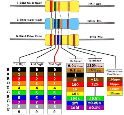
Color coding of resistance
 |
| Google image by: https://www.instructables.com/id |
 |
| Combination of resistance |
In figure(a), current I flows through three resistances. Applied voltage V must be equal to the sum of the three individual voltage drops V1,V2, V3.
V =V1+V2+V3
= IR1+IR2+IR3
=I (R1+R2+R3)
V=IRs
Where
Rs = R1+R2+R3
2. Parallel combination:
In figure (b), voltage V is equal to all three resistances.
I1=V/R1;I2=V/R2;I3=V/R3
Here,
I = I1+I2+I3
= V(1/R1+1/R2+1/R3)
= V/Rp
1/Rp=(1/R1+1/R2+1/R3)
For two resistances,
1/Rp=1/R1+1/R2=R1R2/(R1+R2)
Voltage Divider Rule:
Voltage division takes place in series circuit.The concept of voltage divider is very useful when analyzing the circuits.
Consider the circuit in which two resistors
R1 and R2 are connected in series with a voltage source V. The current I is
given as:
I =
V /(R1 + R2)
Therefore,
the voltage V1 across resistor R1 is
V1
= IR1 = V R1 /(R1 + R2)
Similarly,
the voltage V2 across resistor R2 is given as:
V2
= IR2 = V R2 /(R1 + R2)
Current
divider rules:
Let
us consider that two resistors (R1 and R2) are connected in parallel.
Therefore, a voltage V appears at both resistor.
V =
I1R1 and V = I2R2
Among
them, I2 = V / R2 = I1 R1 / R2
I =
I1 + I2 = I1 + I1 R1 / R2 = I1 [R1 + R2 / R2]
I1
= IR2 / R1R2
The
current through R2 is given as
I2
= IR1 / R1R2
Kirchhoff's Law
The
German physicist Gustav Kirchhoff (Gustav Kirchhoff) observed that these are
specific examples of analyzing two basic conditions of any power circuit. The
possible conditions are as follows:
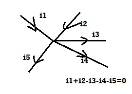
The first Kirchhoff ‘s law is current law(KCL): at any moment, the algebraic sum of the current at the network node is zero.
At any electrical junction incoming current is equal to outgoing current. Different sign positive and negative are assigned to keep the current flowing to and away from the junction.
 |
| Kirchhoff ‘s current law |
The second Kirchhoff ‘s voltage law: In any case in a closed loop, the algebraic sum of e.m.f that works in the loop is equal to the algebraic sum of potential drop in the loop.
 |
| KVL |
Circuit Theorems
- Superposition Theorem
- Thevenin's Theorem
- Norton's Theorem
- Maximum Power Transfer
Superposition
Theorem:
In
any linear, bilateral network having various active and passive element, the
response (current, voltage) across any passive element is algebraic sum of all
the responses across that element when considering one source at a time and
deactivation all other source at that instant.
Because
the circuit is linear, we can find the circuit's response to each source acting
alone, and then add them together to find the circuit's response to all sources
acting together. This is the so-called superposition theorem.
The
principle of superposition states that the voltage across a component (or the
current flowing through it) in a linear circuit is the algebraic sum of the
voltage across the component (or the current flowing through it). This is due
to the fact that each independent power supply works independently. .
Steps
to apply the superposition principle:
1.
Turn off all independent sources except one. Look for the response (voltage or
current) due to a valid source.
2.
Repeat step 1 for each other independent source.
3.
Find the total output by adding all the results found in steps 1 and 2 above
algebraically.
Let us take one example :
#Remedial Lecture-01:Solve 2 Question(Given below) on Basic Law's of Electrical Network & Paste your photo of your solution by Clicking on plus(+)pink sign below.Write your roll no and name on every page of your solution then take photo.
MCQ Test-01Click here for MCQ Test-01. Syllabus of MCQ Test-01:D.C. CIRCUITS AND A.C. CIRCUITS: Classification of network, Ohm's law, KCL, KVL, network simplification using star-delta / delta-star transformations, mesh analysis, network theorems (Superposition and Thevenin).Generation of alternating voltages, fundamentals of ac circuits, behaviour of pure R, L, C in ac circuits, concept of phasor and its representation, series RL, RC and RLC circuits

